Regarding electronic circuits and power supply units, the bridge rectifier plays a crucial role in converting alternating current (AC) to direct current (DC). Ensuring the proper functioning of a bridge rectifier is essential for the overall performance of electronic devices. In this article, we will delve into the significance of testing bridge rectifiers and provide valuable insights for optimizing their operation.
Before we dive into the testing procedures, let’s briefly revisit the fundamentals of a bridge rectifier. The bridge rectifier is a key component in power supply circuits and is responsible for converting AC to pulsating DC. The diodes within the bridge rectifier enable the flow of current in one direction, smoothing out the waveform and providing a consistent DC output.
For those seeking a detailed explanation of the operation, please follow this link for an in-depth look: Full-Wave Bridge Rectifier Operation with Capacitor Filter.
Testing bridge rectifiers is a critical step in ensuring the reliability and efficiency of electronic circuits. Identifying potential issues early on can prevent malfunctions and enhance the lifespan of the overall system. Here are some key reasons why testing is crucial:

Let’s explore the step-by-step process of testing a bridge rectifier using a digital multimeter. This simple yet effective method can help you diagnose potential problems quickly.
Reversed Biase
Forward Biase
The post Learn and Master Testing a Bridge Rectifier for Optimum Performance appeared first on Electric Shocks.
Understanding the Basics:
Before we dive into the testing procedures, let’s briefly revisit the fundamentals of a bridge rectifier. The bridge rectifier is a key component in power supply circuits and is responsible for converting AC to pulsating DC. The diodes within the bridge rectifier enable the flow of current in one direction, smoothing out the waveform and providing a consistent DC output.
- Advancing Electronics Manufacturing: Overview of PCB Assembly Process
- Comparison of MOSFET vs Other Electronic Components
For those seeking a detailed explanation of the operation, please follow this link for an in-depth look: Full-Wave Bridge Rectifier Operation with Capacitor Filter.
Why Testing is Crucial:
Testing bridge rectifiers is a critical step in ensuring the reliability and efficiency of electronic circuits. Identifying potential issues early on can prevent malfunctions and enhance the lifespan of the overall system. Here are some key reasons why testing is crucial:
- Fault Detection: Testing allows for detecting faulty diodes or other components within the bridge rectifier. Identifying and replacing defective parts can prevent circuit failures and ensure a stable power supply.
- Performance Optimization: By testing the bridge rectifier, you can fine-tune its operation for optimal performance. This involves checking for voltage drops, ensuring proper current flow, and validating that the rectifier meets the specified electrical parameters.
- Preventing Overheating: Overheating is a common issue in electronic components. Through testing, you can identify any signs of excessive heat in the bridge rectifier and take preventive measures to avoid potential damage.
How to Test a Bridge Rectifier with a Digital Multimeter:
Let’s explore the step-by-step process of testing a bridge rectifier using a digital multimeter. This simple yet effective method can help you diagnose potential problems quickly.
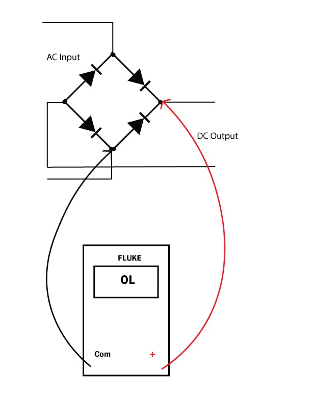
Reversed Biase
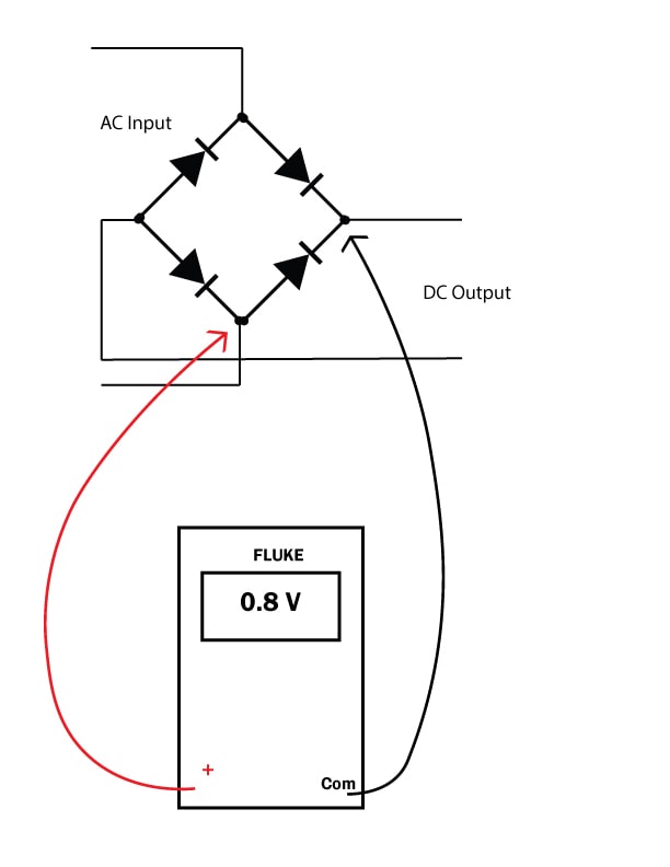
Forward Biase
- Safety First: Before testing, always ensure the power to the circuit is turned off. Safety is paramount when dealing with electronic components.
- Multimeter Settings: Set your digital multimeter to the diode/continuity testing mode. This mode allows the multimeter to measure the voltage drop across the diode, providing insights into its health.
- Diode Identification: Bridge rectifiers consist of four diodes, and it’s essential to identify them. Refer to the rectifier’s datasheet or circuit diagram to locate the anode and cathode of each diode.
- Testing Individual Diodes: Place the multimeter’s positive probe on the anode and negative on the cathode of each diode. A healthy diode should display a voltage drop of around 0.5 to 0.7 volts. The diode may be faulty if the reading is significantly lower or higher.
- Reverse Polarity Test: Swap the multimeter probes, placing the positive probe on the rectifier’s cathode terminal and vice versa. The voltage drop should be extremely high. If the multimeter shows a low voltage drop, it indicates a faulty diode.
- Check for Short Circuits: Use the multimeter in resistance mode to check for short circuits across the bridge rectifier input and then output. A low resistance reading may indicate a short circuit. A short circuit means a faulty circuit.
The post Learn and Master Testing a Bridge Rectifier for Optimum Performance appeared first on Electric Shocks.